Q4 FEATURES
Introduction
This quarterly technical report covers the progress made in developing Noisy-AntCity. This sound propagation model allows users to experience the noise generated by eVTOL aircraft from a first-person perspective. We also worked on AntCityVCM, a simulation module for vertiports, and AntCity Industrial Studio, a historian and visualizer for temporal data series curves. Additionally, we created AntCity Docs, a community content generation portal for AntCity, and AntCity DevOps, an automated tool for creating and deploying infrastructure for AntCity in cloud components. In this report, we will discuss each project's achievements, challenges, and future plans in detail.
Noisy-AntCity
Noise can be defined as "unwanted sound" FEDERAL AVIATION ADMINISTRATION, 2021. Therefore, noise has objective and physical components, such as intensity. The subjective component considers the individual perception or reaction to the sound. The Noisy-AntCity subsystem allows for the visualization of the physical components of sound and enables the user to experience exposure to noise.
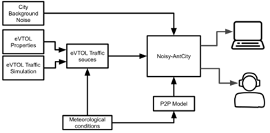
The implementation of the sound propagation model (WATTS & Morgan, 2002), enabling prediction and visualization of the environmental sound generated by eVTOL traffic. While the FAA has specialized models such as the Integrated Noise Model INM (Federal Aviation Administration, 2005) and the Aviation Environmental Design Tool AEDT (Federal Aviaton Administration, 2015), these focus on noise generation rather than propagation. The implementation of Noisy-AntCity is based on the model described in the paper by Salomons et al. (Salomons, Maercke, Defrance, & Roo, 2011) , which details the mathematics for simulating point-to-point sound propagation. The described model is easy to implement and proper for sound propagation visualization in a city.
Noisy-AntCity allows real-time visualization of the sound propagation model output through color gradients corresponding to dB sound levels overlaid on the 3D representation of the city. Additionally, the system can visualize the temporal dimension component (figure 1) by utilizing the city and AntCity Industrial Studio representation to analyze its temporal dimension.
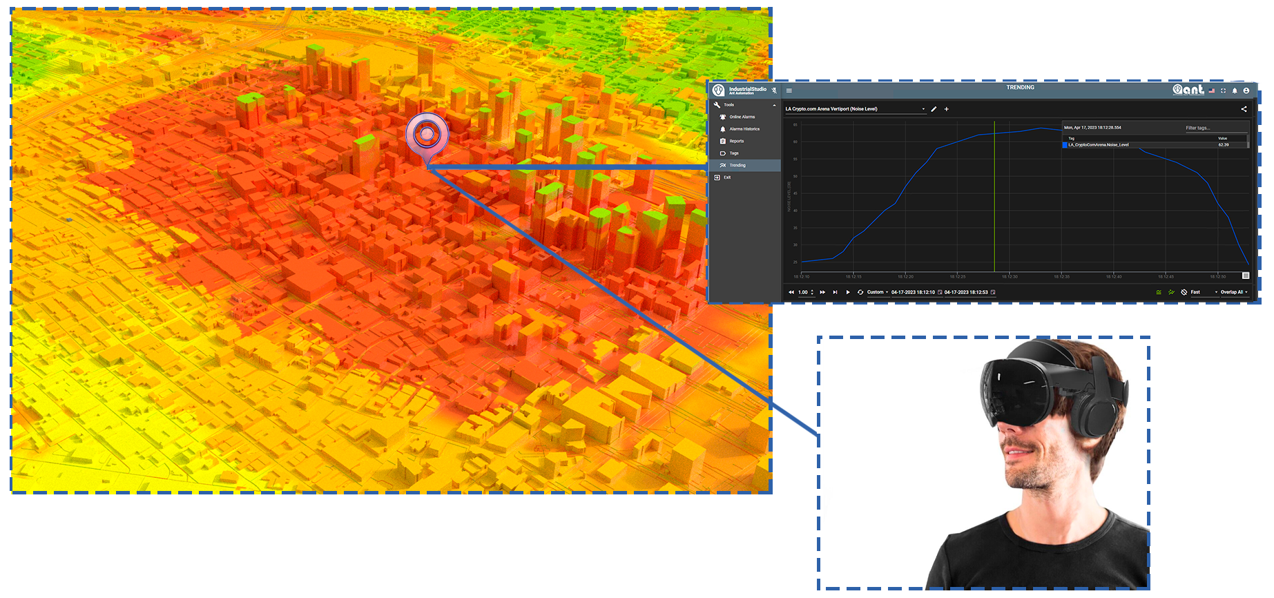
The human ear responds differently to sound pitches or frequencies. We are less able to hear low frequencies like the rumble of thunder but more sensitive to high frequencies like the cry of a baby or the sound of small drone engines. Noisy-AntCity enables a first-person experience of eVTOL noise emission at any point in a city and the visualization of the A-weighted metric (dBA) in a time series curve. This scale closely approximates the relative volume of sounds the human ear perceives. It provides a valuable way of evaluating the effect of noise exposure on humans by focusing on those parts of the spectrum where we are most sensitive.
The Noisy-AntCity noise propagation model has two main aspects: (a) Path detection, which involves organizing the entire dataset into cross-sections representing all possible sound paths between sources and receivers. These cross-sections must be geometrically formatted according to the algorithms and definitions outlined in the calculation standard (Banda & Stapelfeldt, 2007) ; and (b) Path calculation, which entails applying the calculation algorithms described to the cross-sections (Banda & Stapelfeldt, 2007).
Vertiport Configuration Module (AntCityVCM)
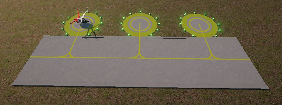
AntCityVCM can capture and display a vertiport's technical specifications for operation with manned eVTOL aircraft. It uses 3D models to accurately render the vertiport's physical environment, including the landing and take-off areas, access roads, and any surrounding obstacles.
AntCityVCM incorporates data on the dimensions and weight capacity of the eVTOL aircraft being used, as well as information on the operational requirements of the vertiport, such as fueling and maintenance facilities. Additionally, AntCityVCM uses AR and VR technology to provide a more immersive experience for users, allowing them to explore the vertiport in greater detail and visualize how it would function in a real-world scenario. AntCityVCM provides a valuable tool for planners, engineers, and other stakeholders developing this emerging technology.
The 3D model is stored in the Content Server of the Digital Asset Management (DAM) System (Ant Automation LLC, 2023). The properties of the vertiport are stored in the module's data model. This approach enables the efficient management of vertiport data and facilitates the vertiport integration into AntCity. Separating the 3D model from its properties makes it possible to make changes to either element independently. This approach ensures that the model and properties remain consistent, even with updates or modifications. Additionally, using the DAM system allows for easy access to the 3D model by other components of the AntCity system, such as the simulation engine, which can use the model to test the performance of the vertiport under various conditions.
eVTOL Data
The module not only stores the specific properties of the Vertiports but also can store the properties of the eVTOLs, including the necessary data for safe and efficient operations (EASA, 2021):
- (1) dimensions: shape/configuration;
- (2) maximum take-off mass (MTOM);
- (3) request for a lateral maneuvering area during take-off from a final-approach and take-off area (FATO) to a take-off decision point (TDP) (including synthetic means, i.e. cameras to ensure the approach and take-off path);
- (4) approach/departure paths compared to obstacle limitation surfaces (OLSs) (International Civil Aviation Organization, 2019);
- (5) rejected take-off distance (RTOD), characteristics of the load-bearing surface needed for rejected take-off (RTO);
- (6) landing gear geometry and dimensions, minimum ground turn radius;
- (7) VTOL taxiing, ground movement and parking requirements (specify the moving infrastructure for VTOL-capable aircraft, and whether the ‘D-value’ changes from landing to taxiing and parking);
- (8) visual angle in the vertical plane through pilot eye position
- (9) minimum handling-area requirements around the VTOL-capable aircraft, including passenger handling and areas anticipated for the VTOL-capable aircraft services (i.e. battery charging, swap area, and the like).
Vertiport Data
The AntCityVCM data model can store the following data related to the dimensions and related information of the Vertiport:
- (1) Vertiport reference point (VRP), means the designated geographical location of a vertiport;
- (2) the elevation of the touchdown and lift-off area (TLOF) and/or the elevation and geoid undulation of each final-approach and take-off area (FATO);
- (3) vertiport type: surface level or vertiport that is elevated;
- (4) TLOF: dimensions to the nearest meter, slope, surface type and bearing strength to the nearest 100 kg;
- (5) FATO: type of FATO, true bearing to one-hundredth of a degree, designation number (where appropriate), length and width to the nearest meter, slope, and surface type;
- (6) SA: length, width, and surface type;
- (7) VTOL-capable aircraft taxiway and taxi-route: designation, width, and surface type;
- (8) maximum D-Value and maximum take-off mass (MTOM) allowed; apron: surface type and VTOL-capable aircraft stands;
- (9) clearway (if provided): length, ground profile or, when elevated, height above the FATO, and length and width;
- (10) visual aids for approach procedures, marking and lighting of the FATO, TLOF, VTOL-capable aircraft taxiways, air taxiways, taxi-routes, and stands;
- (11) The geographical coordinates of appropriate center line points of VTOL-capable aircraft taxiways;
- (12) the geographical coordinates of obstacles in Area 2 (the part within the vertiport boundary) and in Area 3.
The data model contains properties for the following distances related to the Vertiport:
- (1) landing distance available (LDAV),
- (2) landing distance required (LDRV),
- (3) rejected take-off distance available (RTODAV),
- (4) rejected take-off distance required (RTODRV),
- (5) rejected take-off distance (RTODV),
- (6) take-off distance available (TODAV), and
- (7) take-off distance required (TODRV).
To serve as a tool to assess safety measures, the AntCityVCM data model also includes a set of key dimensions:
- (1) vertiport elevation
- (2) TLOF size,
- (3) FATO size,
- (4) SA size,
- (5) clearway,
- (6) distance from the SA or clearway perimeter to the vertiport edges, and approach/departure paths showing locations of buildings, trees, fences, power lines, obstructions (including elevations), schools, places of worship, hospitals, residential areas, and other significant features.
Vertiport 3D Model
In AntCity, user-provided 3D models consist of "defined" or "subsidiary" areas, the basic building blocks for the design process. Each area is defined by its purpose, limitations, and attributes.
The 3D model design should follow the principles of encapsulation, which means that each area can be positioned independently or in combination with any other defined or subsidiary area.
The defined areas include
- (1) the final approach and take-off area (FATO);
- (2) the touchdown and lift-off area (TLOF); and
- (3) the stand, taxiway, ground taxi-route, and air-taxi-route areas.
The subsidiary areas include
- (1) the Safety Area (SA);
- (2) the clearway; and
- (3) the Protection Area, which is a defined area surrounding a stand that is intended to reduce the risk of damage from eVTOL accidentally diverging from the stand.
These defined and subsidiary areas and their associated attributes and limitations serve as a framework for evaluating safety measures and designing efficient and effective vertiports.
Vertiport Obtacle Limitation Surfaces
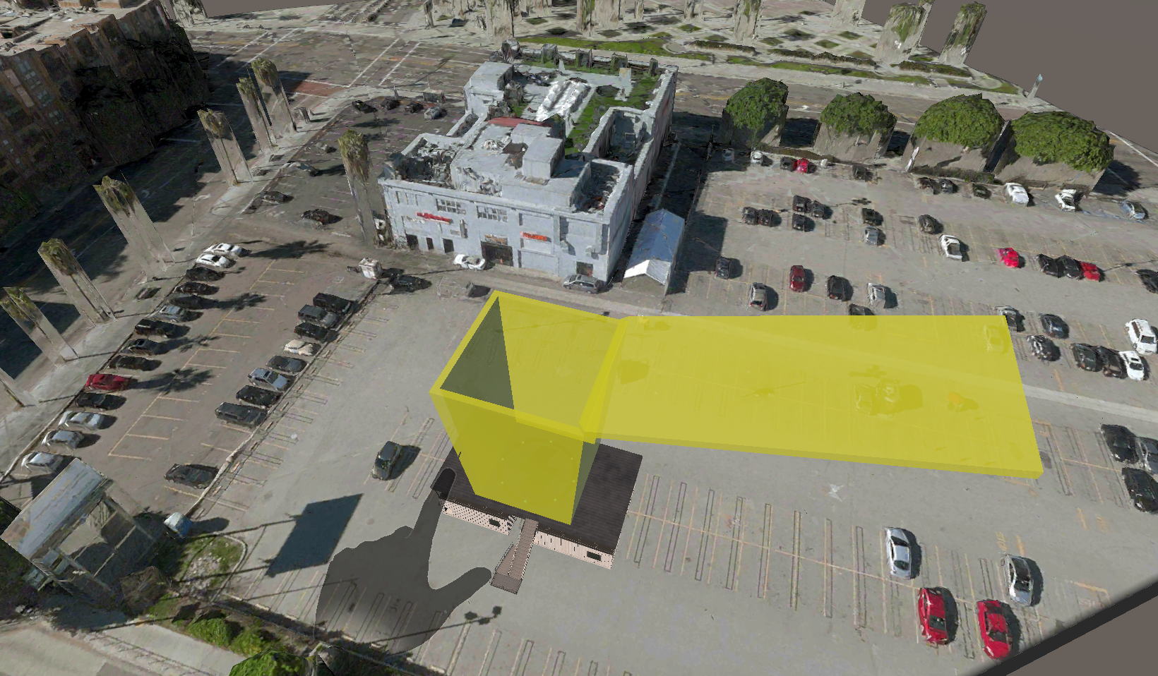
AntCityVCM stores the necessary data for displaying obstacle-free surfaces (International Civil Aviation Organization, 2019) required during the eVTOL approach to the FATO area and its elevation after take-off (approach and take-off climb surface). For each Vertiport, the shape can be stored in GeoJSON format (Internet Engineering Task Force IETF, 2016), already utilized in the AntCityAM module (Ant Automation LLC, 2023) If these surfaces involve turns, the module can represent a complex surface containing the horizontal normal to its center line, and the slope of the center line should be the same as that for a straight approach surface.
The types of surfaces that can be specified are (1) Approach surface; (2) Transitional surface, designed to provide protected airspace when vertical procedures include lateral transit; (3) the take-off climb surface is intended to protect an eVTOL aircraft during take-off and during climb-out. In addition to the surfaces defined for helipads (International Civil Aviation Organization, 2019) , it is possible to determine an obstacle-free volume (OFV) in AntCityVCM. This volume aims to provide protection above, enabling the introduction of vertiports in congested areas with obstacle-populated environments for eVTOL aircraft. The corresponding procedure is designated as ‘vertical take-off and landing’. Due to the reduced footprint and vertical nature of the take-off and landing, synthetic cues may have to be used to guide the aircraft.
AntCity Industrial Studio
The curve viewer tool developed this quarter has provided a valuable addition to the Spatiotemporal Data Module for eVTOL flight data analysis (Ant Automation LLC, 2023). The tool allows for the exploration of the temporal aspect of the data and provides a more comprehensive understanding of eVTOL flight patterns, operation delays (figure 5), and noise levels near vertiports. Integrating the tool with the Spatiotemporal Data Module allows for efficient and effective data analysis.
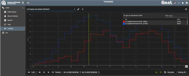
When visualizing data in the form of curves, it is possible to: (a) identify patterns and trends that may not be evident when simply looking at numbers, such as identifying if there is a pattern of recurrent delays at certain times of the day or days of the week; (b) display multiple variables simultaneously, allowing for comparison and seeing how they relate; (c) a curve can highlight anomalies that may be important in the analysis -for example, if a delay curve shows a sudden drop or increase at a specific time, this could indicate a problem that needs investigation; (d) it is an easy-to-use tool, even for people without experience in data analysis.
In summary, AntCity Industrial Studio is a valuable tool for analyzing time-series data from simulations, as in the case of delays in the departures and arrivals of VTOL flights at a vertiport. It enables pattern identification, comparison of different variables, detection of anomalies, and is user-friendly even for individuals without prior experience in data analysis.
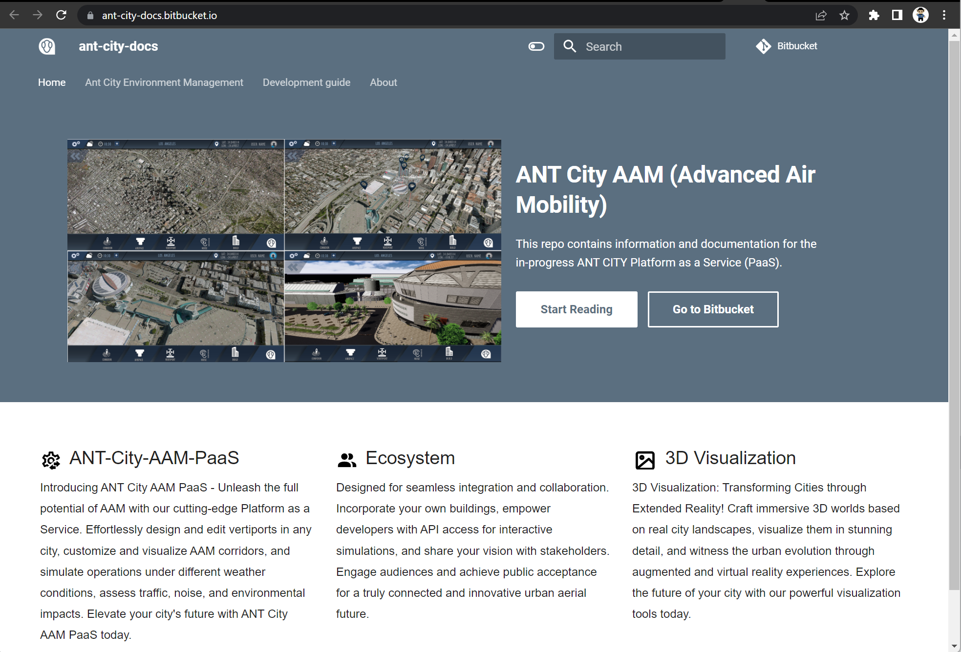
AntCity Docs
Implementing a community documentation module such as AntCity Docs enables the formation of a user community. AntCity Docs aims to achieve the following goals: (a) to create a vast knowledge base where users generate information on a variety of topics, which means that the compiled and shared information can be beneficial for both users and developers of the system; (b) to encourage collaboration among AntCity users and developers to share information, troubleshoot problems, and continuously improve the system; (c) to form a community of users through a community documentation system, which can be very valuable to users and developers, as it can help to enhance the system and provide a continuous source of feedback; and (d) to ensure accessibility, AntCity Docs is an online platform that can be accessed from anywhere with an internet connection, which means that information about AntCity can be easily accessed by anyone interested in the subject, from anywhere in the world.
AntCity DevOps
AntCity DevOps is a new AntCity subsystem consisting of applications and tools to automate the deployment and execution of cities in the cloud. The metamodel, language, and tools components of AntCity DevOps were designed and developed to enable the deployment of cities on virtual machines and containers in different cloud vendors.
A computational asset is any technological artifact capable of running AntCity's active components or applications, such as virtual machines, containers, or serverless functions. AntCity DevOps operates on Azure and uses two different types of computational assets: Azure Virtual Machines and Docker Containers deployed in Kubernetes (using the Azure Kubernetes Service).
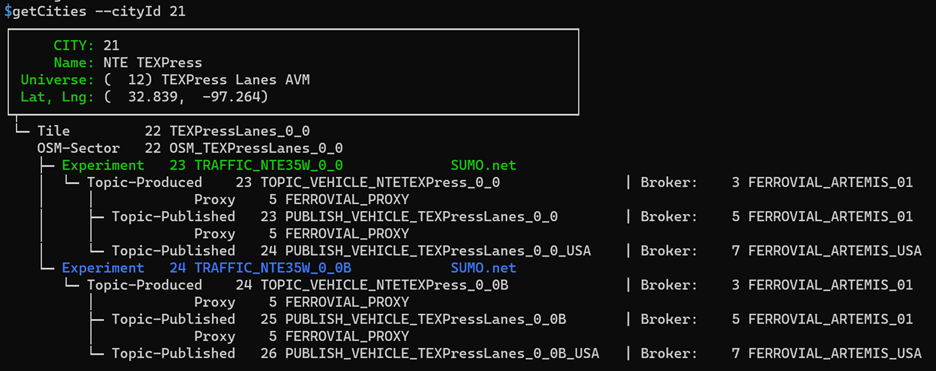
A command-line application was built allowing users to create computational assets, deploy active components, and start and stop them. Figure 7 shows the execution of the command that displays the applications that make up a city.
Internally, the tool utilizes a series of practices known as Infrastructure as Code (IaC) that use "code" to set up (virtual) machines and networks, install packages, and configure the environment for the digital twin (Len Bass, 2015). This code's infrastructure includes physical equipment ("bare metal") and virtual machines, containers, and software-defined networks. It enables developers to treat infrastructure as software, meaning they can automate the process of deploying and managing infrastructure, reducing the potential for human error, and increasing efficiency. Using IaC, infrastructure resources such as virtual machines, networks, and storage can be defined and managed through code. This allows teams to reproduce environments, test and validate changes, and quickly deploy updates faster and reliably.
Conclusions and Next Steps
In addition to the work detailed in the previous sections, we have made significant progress in improving the Augmented Reality (AR) and Virtual Reality (VR) interfaces, enhancing the user experience and implementing feedback for the new Noisy-AntCity and AntCityVCM modules.
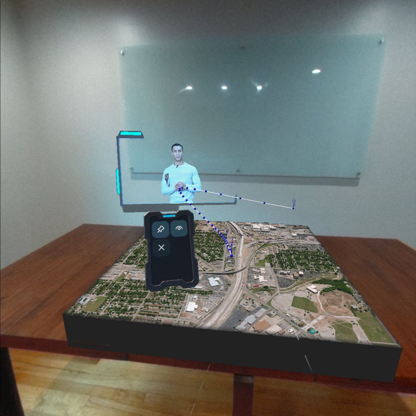
Furthermore, we have also worked on the user interface for the interactive creation of air corridors in the AntCity Airspace Module (AM) and in an AI assistant (figure 8) that guides an inexperienced user through the flight route creation process in the AR and VR interface. It provides step-by-step instructions, reduces errors, ensures safety, increases efficiency, and improves the overall user experience. Additionally, it enables the user to focus on the flight experience rather than the technicalities of creating a flight path, resulting in a more enjoyable and immersive experience. Moving forward, in the next quarter, we will continue to focus on enhancing these interfaces, building on our progress thus far.
Additionally, we will begin creating a user interface in augmented reality to configure vertiports in the AntCityVCM module presented in this report.
We are confident that these efforts will further improve the usability and accessibility of AntCity and help us to continue to innovate in the rapidly evolving field of urban air mobility.